DemonstratesLaat Zien
Patch Panel Re-TerminationPatchpanel Herafmontage
Shows physical rack work, punch-down process, labeling, and post-fix verification.Toont fysiek rackwerk, punch-down-proces, labeling en verificatie na de fix.
Ports T1-T3 (sanitized example). Structure and technical content mirror the reference DOCX.Poorten T1-T3 (geschoond voorbeeld). Structuur en technische inhoud volgen het referentie-DOCX.
Recruiter SummaryRecruiter Samenvatting
A documentation-first structured cabling case study covering fault identification, re-termination, continuity checks, labeling, and switch connectivity proof. Een documentatie-eerste structured-cabling case study over foutidentificatie, herafmontage, continuiteitscontroles, labeling en switch-connectiviteitsbewijs.
DemonstratesLaat Zien
Patch Panel Re-TerminationPatchpanel Herafmontage
Shows physical rack work, punch-down process, labeling, and post-fix verification.Toont fysiek rackwerk, punch-down-proces, labeling en verificatie na de fix.
Working StackWerkende Stack
Patch Panel / Tester / Punch-Down / LabelsPatchpanel / Tester / Punch-Down / Labels
Built around continuity testing, T568B consistency, and end-to-end connectivity checks.Gebouwd rond continuiteitstesten, T568B-consistentie en end-to-end connectiviteitscontroles.
EvidenceBewijs
Step Photos + Tables + .docxStapfoto's + Tabellen + .docx
The page combines procedure steps, validation tables, and a downloadable case study.De pagina combineert procedurestappen, validatietabellen en een downloadbare case study.
Current StateHuidige Status
Live Sanitized Case StudyLive Geschoonde Case Study
Published with anonymized identifiers while preserving the real workflow and verification logic.Gepubliceerd met geanonimiseerde identifiers terwijl de echte workflow en verificatielogica behouden blijven.
Patch Panel Re-Termination & Verification for ports T1-T3 (sanitized example). This technical record documents identification, re-termination, validation, and switch connectivity proof.Patchpanel herafmontage en verificatie voor poorten T1-T3 (geschoond voorbeeld). Dit technisch dossier documenteert identificatie, herafmontage, validatie en connectiviteitsbewijs naar de switch.
This is a sanitized portfolio example. Real site names, room names, services, and exact port mappings have been removed or generalized.Dit is een geschoond portfolio-voorbeeld. Echte sitenamen, ruimtenamen, services en exacte poortmappings zijn verwijderd of gegeneraliseerd.
Reason / Trigger:Reden / Trigger: No link on target patch panel ports T1-T3.Geen link op doelpoorten T1-T3 van het patchpanel.
Re-terminate and verify three network cable runs (T1-T3 shown as example identifiers) on the patch panel. Confirm continuity and correct termination, then label ports and prove end-to-end connectivity by patching from the patch panel to the switch.Monteer drie netwerkkabeltrajecten opnieuw af en verifieer ze op het patchpanel (T1-T3 als voorbeeldidentifiers). Bevestig continuiteit en correcte afmontage, label daarna de poorten en toon end-to-end connectiviteit aan door van patchpanel naar switch te patchen.
This procedure covers identifying runs P13-P15, initial testing, removing the patch panel, punching down cable pairs, reinstalling the panel, re-testing, labeling, and final switch connectivity checks.Deze procedure behandelt het identificeren van trajecten P13-P15, eerste testen, verwijderen van het patchpanel, afmonteren van aderparen, herinstallatie van het panel, hertesten, labelen en de laatste switch-connectiviteitscontroles.
Follow patch panel legend and use same standard on both ends (T568B in this example).Volg de patchpanel-legenda en gebruik aan beide kanten dezelfde standaard (in dit voorbeeld T568B).
Step 1Stap 1
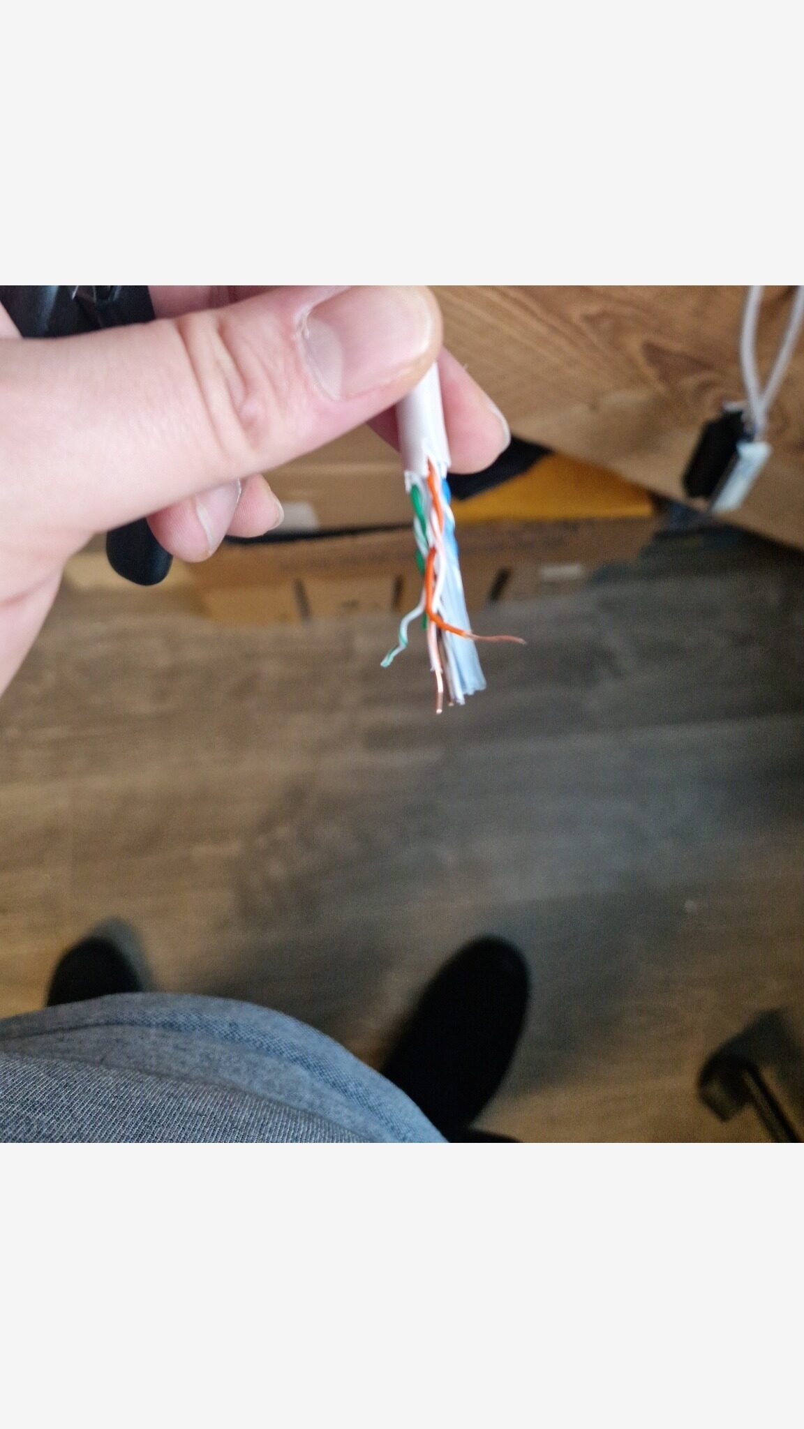
Locate incoming cables for ports P13, P14, and P15. Confirm labels on sheath when available.Zoek de inkomende kabels voor poorten P13, P14 en P15. Controleer waar mogelijk de labels op de kabelmantel.
Step 2Stap 2
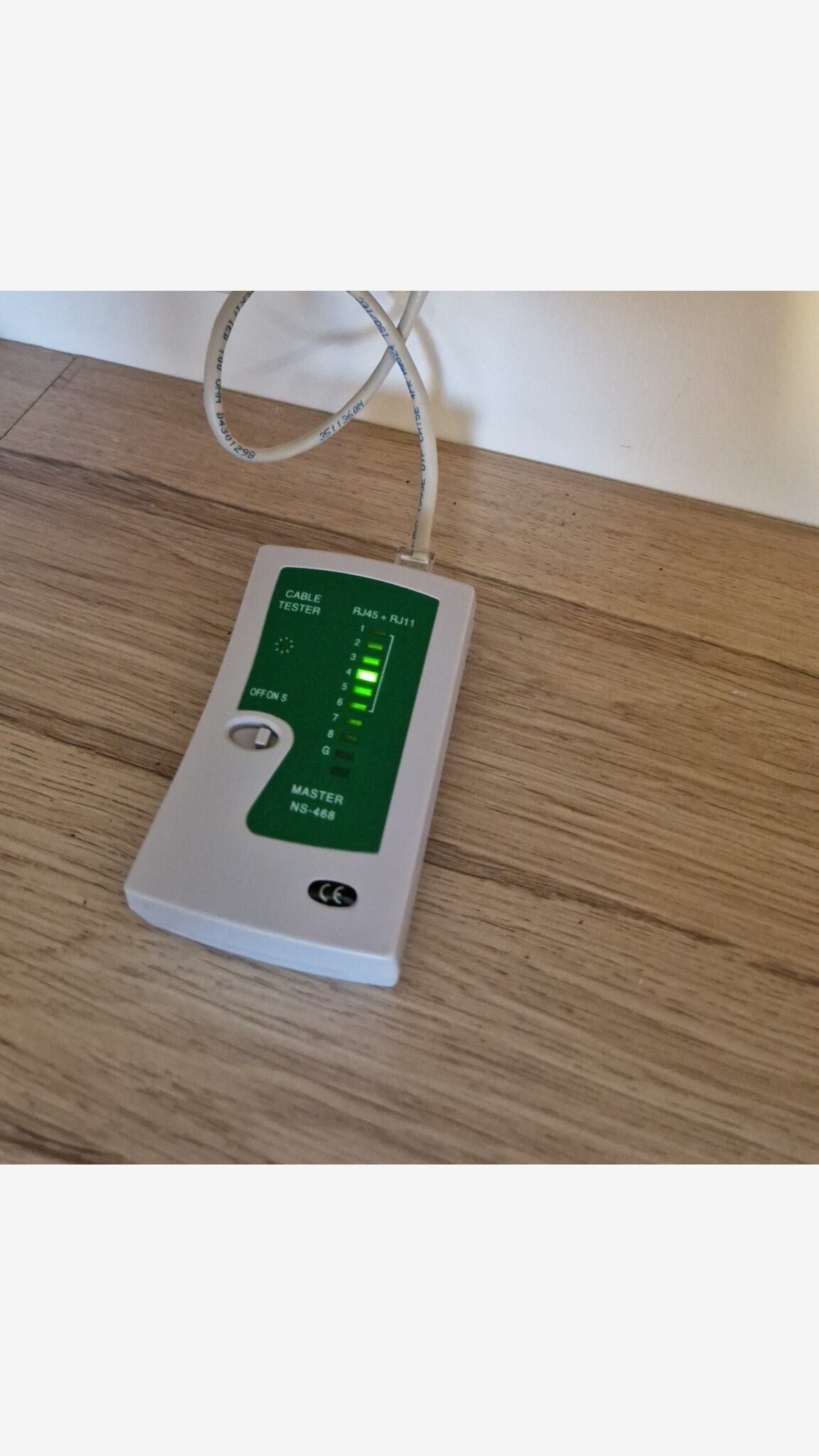
Before any change, test each run using cable tester (master + remote). A successful result is a clean 1 -> 8 sequence.Test elk traject met de kabeltester (master + remote) voordat je iets wijzigt. Een geslaagd resultaat is een schone 1 -> 8-sequentie.
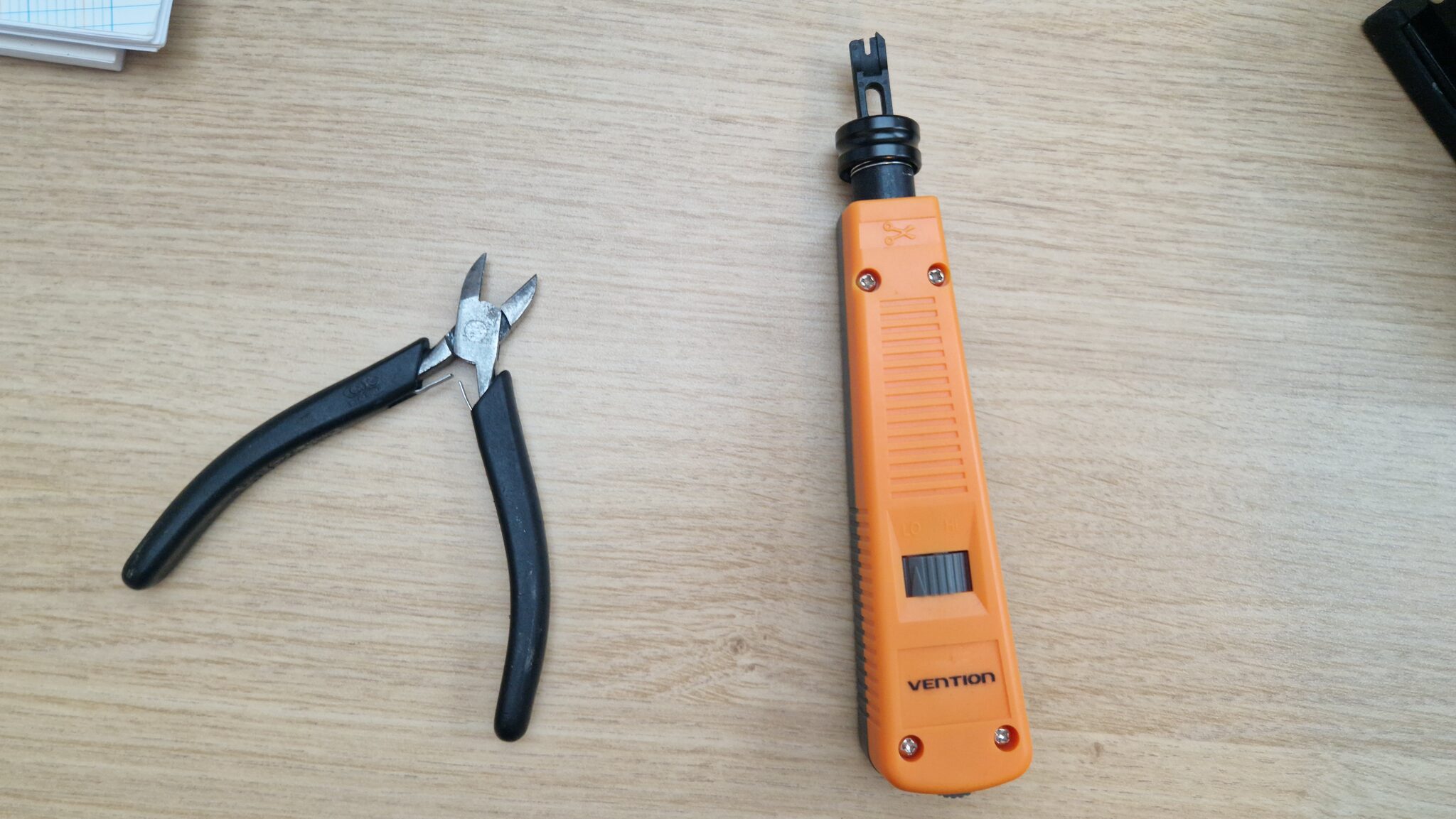
Step 3Stap 3
Step 4Stap 4
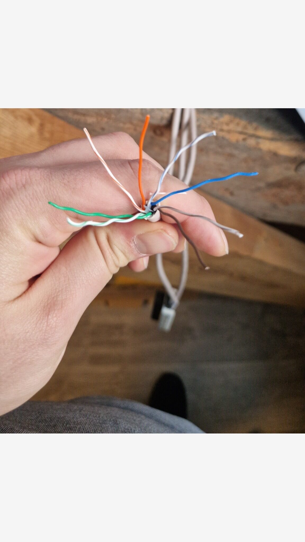
Strip only what is needed and keep pair twists close to punch points.Strip alleen wat nodig is en houd de twists zo dicht mogelijk bij de punch-punten.
Step 5Stap 5
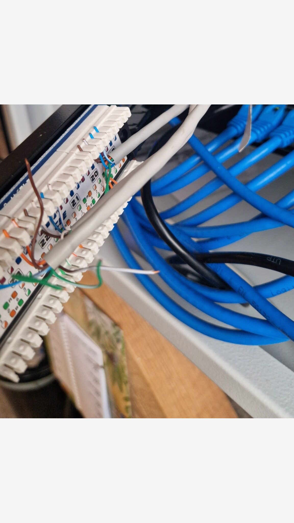
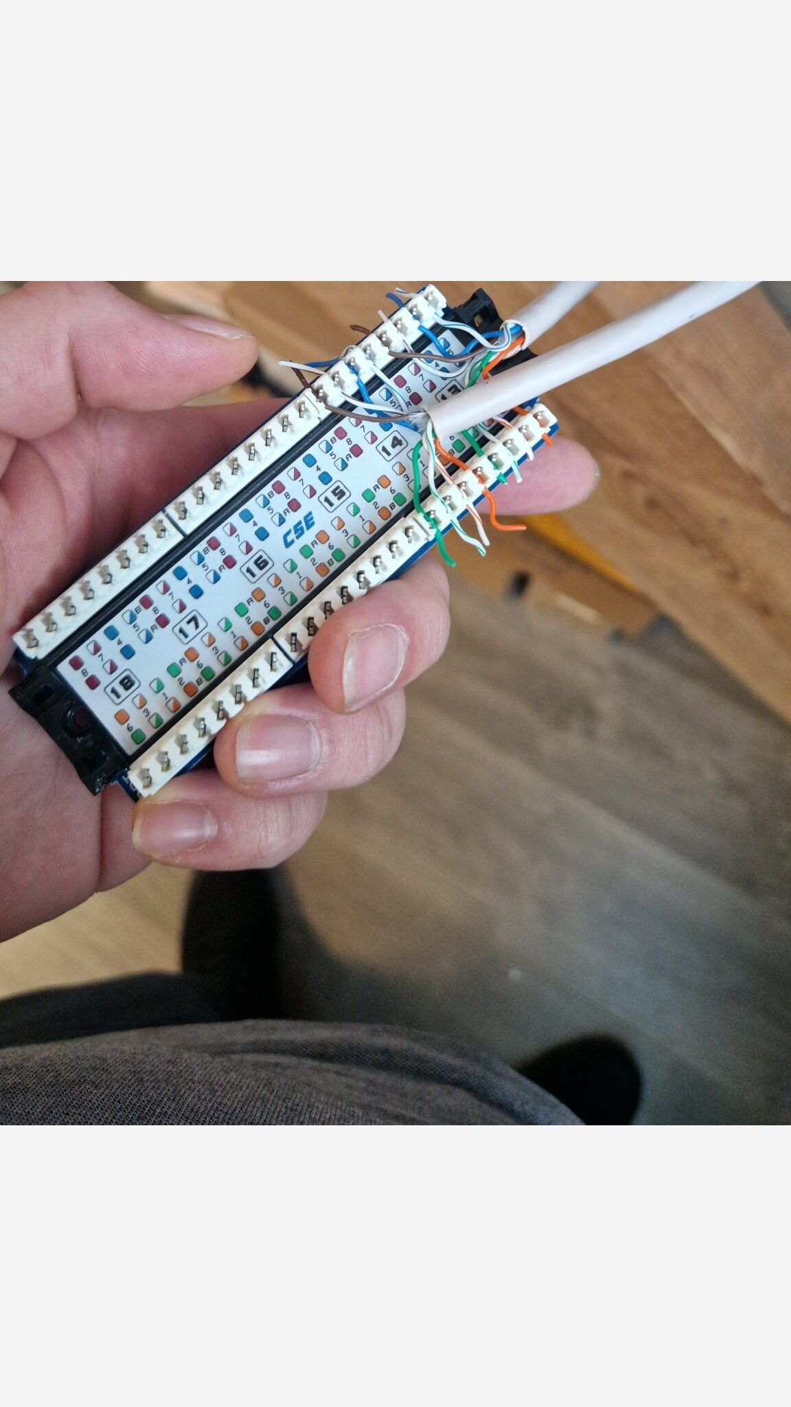
Place conductors in correct IDC slots per TIA-568B legend and punch down. Trim excess conductors.Plaats aders in de juiste IDC-sleuven volgens TIA-568B en monteer af. Knip overtollige aderuiteinden af.
Step 6Stap 6
Terminate all three runs using the same T568B standard consistently.Monteer alle drie de trajecten consequent af volgens dezelfde T568B-standaard.
Step 7Stap 7
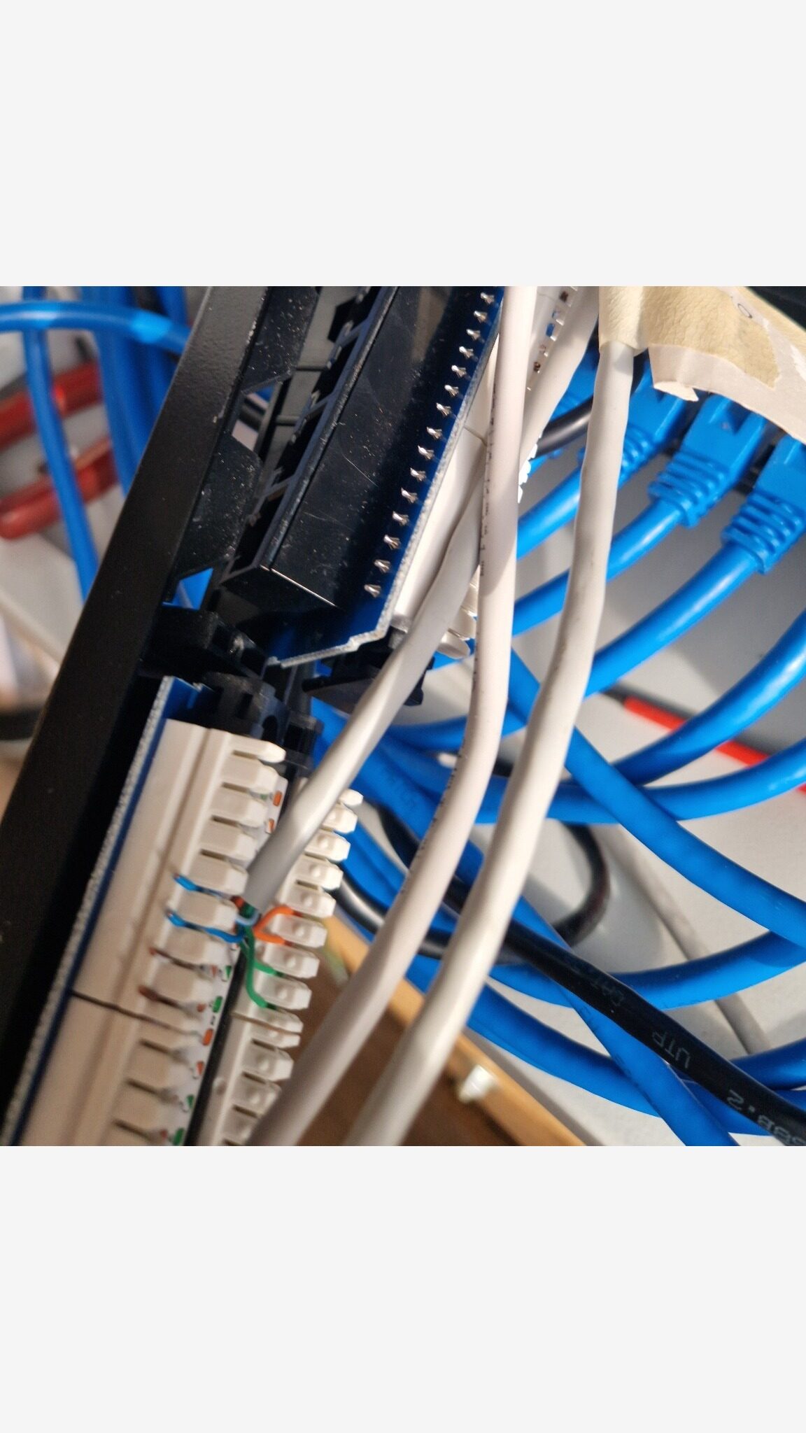
Reinsert modules, reinstall screws and clips, and remount panel in rack.Plaats modules terug, monteer schroeven en clips opnieuw en plaats het panel terug in het rack.
Step 8Stap 8
Re-test ports T1-T3 after re-termination. Expected result: successful (1-8 sequential).Test poorten T1-T3 opnieuw na herafmontage. Verwacht resultaat: geslaagd (1-8 sequentieel).
Step 9Stap 9
Label patch panel ports as T1, T2, and T3 and record corresponding destination/outlet references.Label patchpanelpoorten als T1, T2 en T3 en registreer de bijbehorende bestemmings-/aansluitpuntreferenties.
Step 10Stap 10
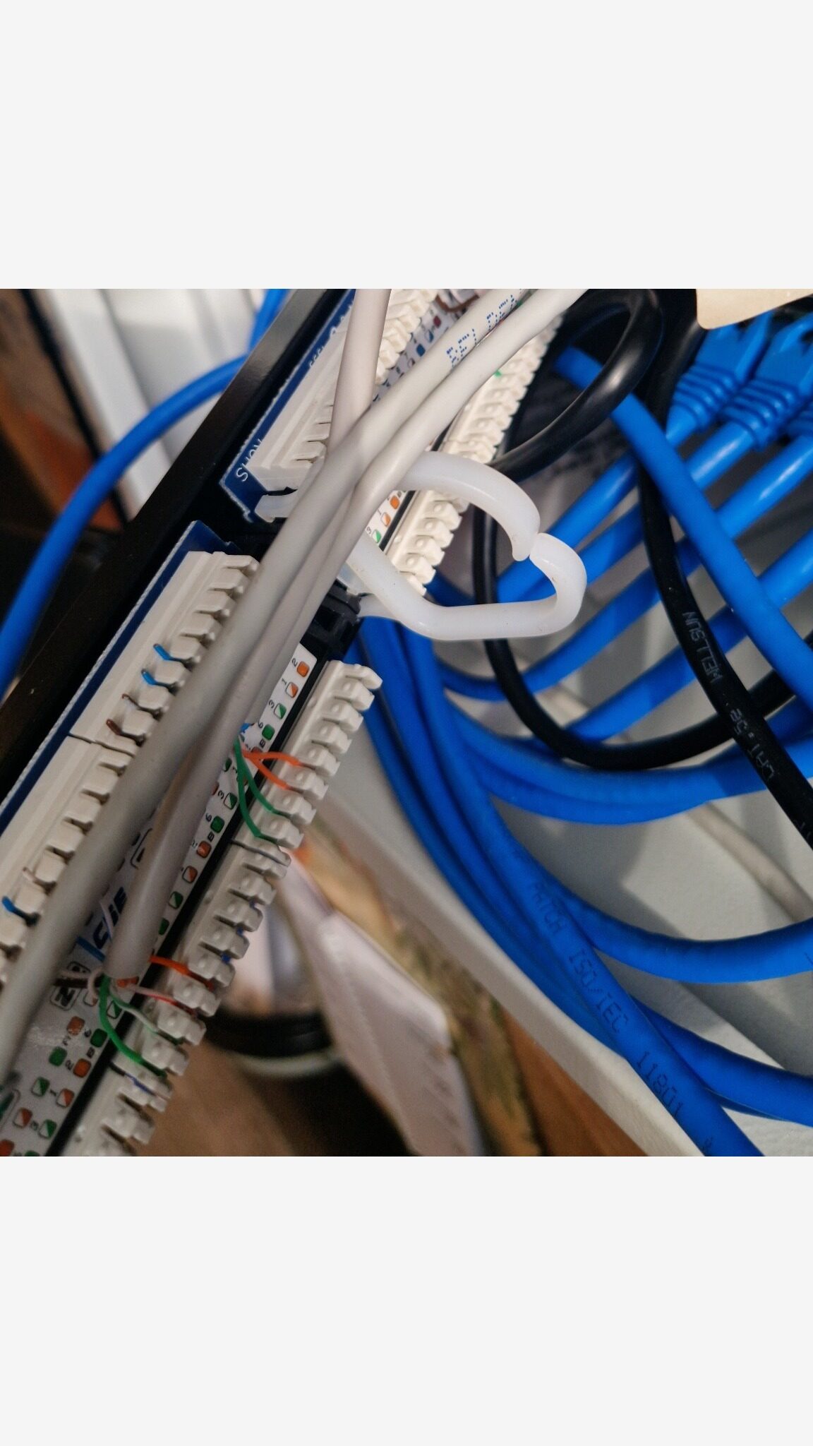
Patch T1-T3 from panel to switch and verify link LEDs plus connectivity proof (DHCP, ping, or MAC table).Patch T1-T3 van panel naar switch en controleer link-leds plus connectiviteitsbewijs (DHCP, ping of MAC-tabel).
Randomized sample data disclaimer: this table is portfolio sample data (P1-P18), not real site mapping.Disclaimer willekeurige voorbeelddata: deze tabel bevat portfoliovoorbeelddata (P1-P18), geen echte sitemapping.
| Zone / OutletZone / Aansluitpunt | Patch panel port #Patchpanel poort # | Notes / ServiceNotities / Dienst |
|---|---|---|
| Zone B-04 | P1 | Legacy deviceOud apparaat |
| Zone E-05 | P2 | UnassignedNiet toegewezen |
| Zone G-08 | P3 | Lab / test pointLab / testpunt |
| Zone F-05 | P4 | IoT endpoint (generic)IoT-eindpunt (algemeen) |
| Zone C-04 | P5 | - |
| Zone B-01 | P6 | - |
| Zone K-05 | P7 | - |
| Zone E-03 | P8 | - |
| Zone K-02 | P9 | UnassignedNiet toegewezen |
| Zone B-03 | P10 | Spare / reservedReserve |
| Zone K-04 | P11 | - |
| Zone G-01 | P12 | UnassignedNiet toegewezen |
| Zone F-04 | T1 | - |
| Zone F-01 | T2 | - |
| Zone E-08 | T3 | - |
| Zone J-06 | P16 | IoT endpoint (generic)IoT-eindpunt (algemeen) |
| Zone A-01 | P17 | Spare / reservedReserve |
| Zone J-01 | P18 | VoIP endpoint (generic)VoIP-eindpunt (algemeen) |
If tester LEDs do not light, light out of order, or show shorts/crossed pairs, re-check punch-down color order and confirm both ends use T568B. Also inspect for damaged conductors or insufficient punch-down seating.Als tester-leds niet branden, in verkeerde volgorde branden, of shorts/gekruiste paren tonen, controleer dan opnieuw de punch-down kleurvolgorde en bevestig dat beide uiteinden T568B gebruiken. Controleer ook op beschadigde aders of onvoldoende punch-down plaatsing.
| PortPoort | BeforeVoor | Before notesNotities voor | AfterNa | After notesNotities na |
|---|---|---|---|---|
| T1 | Unknown (not recorded)Onbekend (niet vastgelegd) | - | Pass (1-8 sequential)Geslaagd (1-8 sequentieel) | Reterminated T568BOpnieuw afgemonteerd T568B |
| T2 | Unknown (not recorded)Onbekend (niet vastgelegd) | - | Pass (1-8 sequential)Geslaagd (1-8 sequentieel) | Reterminated T568BOpnieuw afgemonteerd T568B |
| T3 | Unknown (not recorded)Onbekend (niet vastgelegd) | - | Pass (1-8 sequential)Geslaagd (1-8 sequentieel) | Reterminated T568BOpnieuw afgemonteerd T568B |
Patch ports T1-T3 to switch ports S1-S3 and verify link plus connectivity proof.Patch poorten T1-T3 naar switchpoorten S1-S3 en verifieer link plus connectiviteitsbewijs.
| Patch panel portPatchpanel poort | Switch portSwitchpoort | Link LEDLink-led | Proof (choose one)Bewijs (kies een) | NotesNotities |
|---|---|---|---|---|
| T1 | S1 | YesJa | Ping gatewayPing gateway | __________________ |
| T2 | S2 | YesJa | Ping gatewayPing gateway | __________________ |
| T3 | S3 | YesJa | Ping gatewayPing gateway | __________________ |
Meet the EngineerOntmoet de Engineer

IT Support - Home LabIT Support - Home Lab
I build hands-on labs to learn enterprise IT properly: networking, Windows Server, virtualization, security hardening, and documentation-first workflows. Ik bouw hands-on labs om enterprise IT goed te leren: netwerken, Windows Server, virtualisatie, security hardening en documentatie-first workflows.